Any logic is a set of connected operators. As when people connect constructors’ bricks to build some figure, linking operators (bricks) in the right order brings you to some logic.
Operator is a construct that performs an action, starting from simple a+b or setting a constant to more complex like process HTML.
Operator consists of:
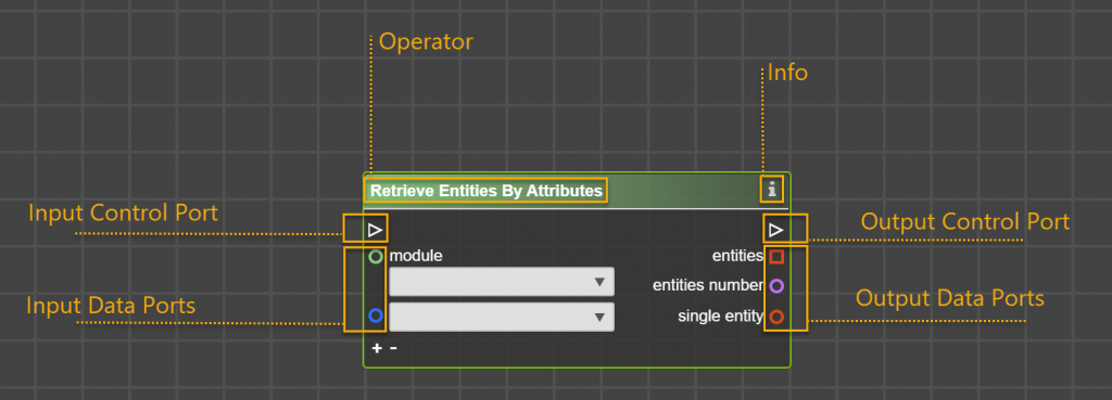
Operator’s Name:
Each operator has a unique name. You can search operators in the menu by name. Commonly the name displays the action that the operator performs.
Info Button:
If you need additional info about the operator – what it does, what ports it has, and so on – simply click on ‘i’ button to receive information directly in Logic Builder.
Control Ports and Control Flow Link:
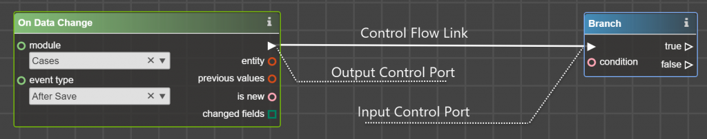
Triangularly shaped ports are called control ports. The link between them is called control flow link.
Simply connect output control ports with input to determine the order of operators’ execution.
Keep in mind several rules:
1. Control flow link only goes in one direction (except loops).
2. If an operator has input control port it must be linked. If port is not linked – an operator won’t be executed, as it is out of control flow.
3. Output control port should be linked, except if it is the last operator of your piece of logic or it is the end of control flow.
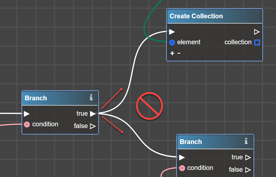
4. You cannot put more than one control flow link from the output control port, except operators which purpose is to divide the flow. It is operators from Control Flow section – Branch, For Each Entity, For each element (these operators have several output control ports).
One control output port = one control flow link!
You cannot:
5. You can link more than one control flow link in the input control port only when control flow comes through one and only one of the control flow links.
Example: You can:
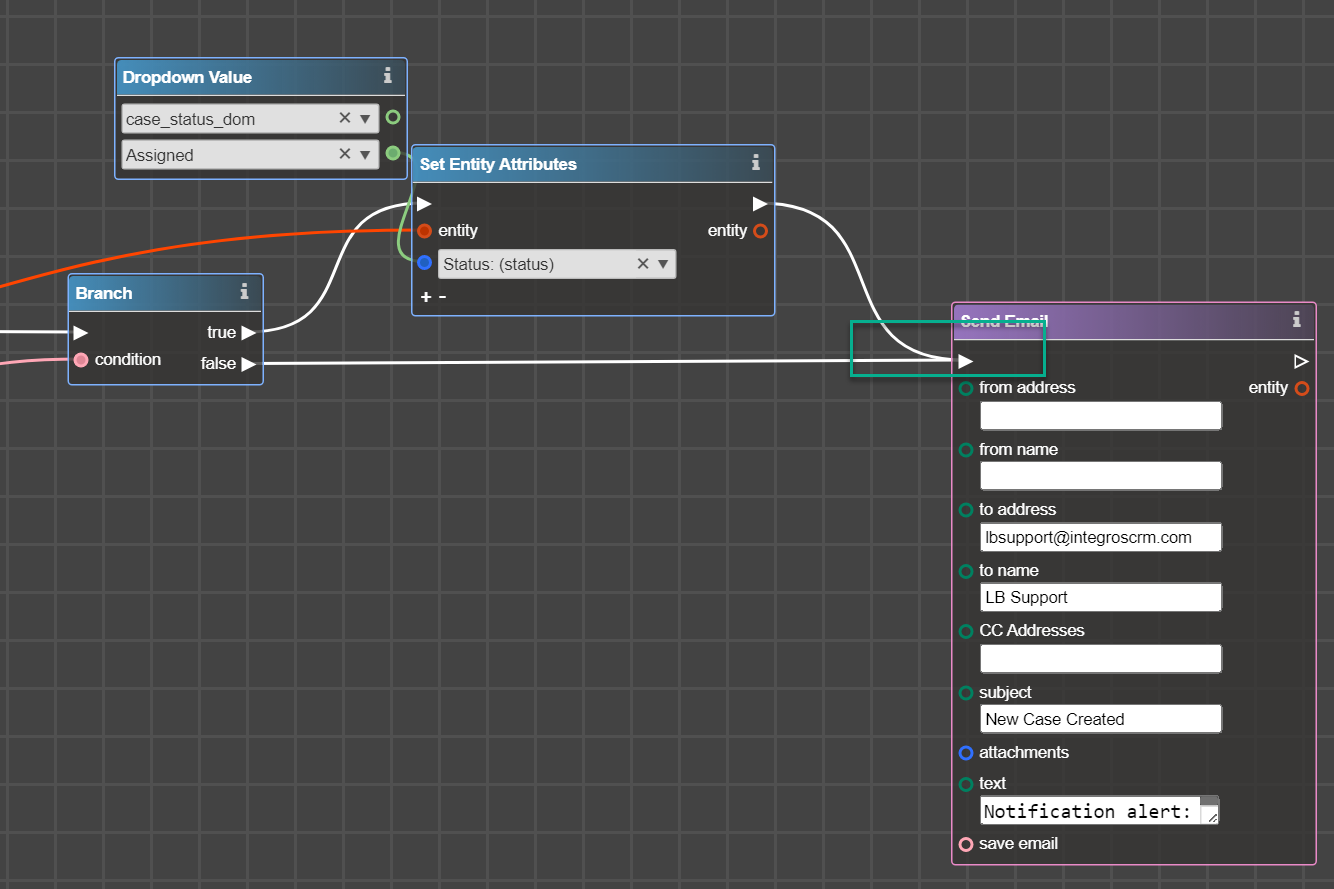
In this example control flow will go either through true -> Set Entity Attributes -> Send Email OR false -> Send Email, but never via both links.
Control Flow in loops and branches
Branch operator has two output control ports – true and false. Control flow always goes through one of them based on a condition – true or false.
Operators For Each Entity or For Each Element has two output control ports – loop body and completed. Control flow keeps coming back to this operator until all the items in the input are gone through the same path down the loop body port. When finished with all the elements, the control flow runs to the control flow link that is connected to its completed control port.
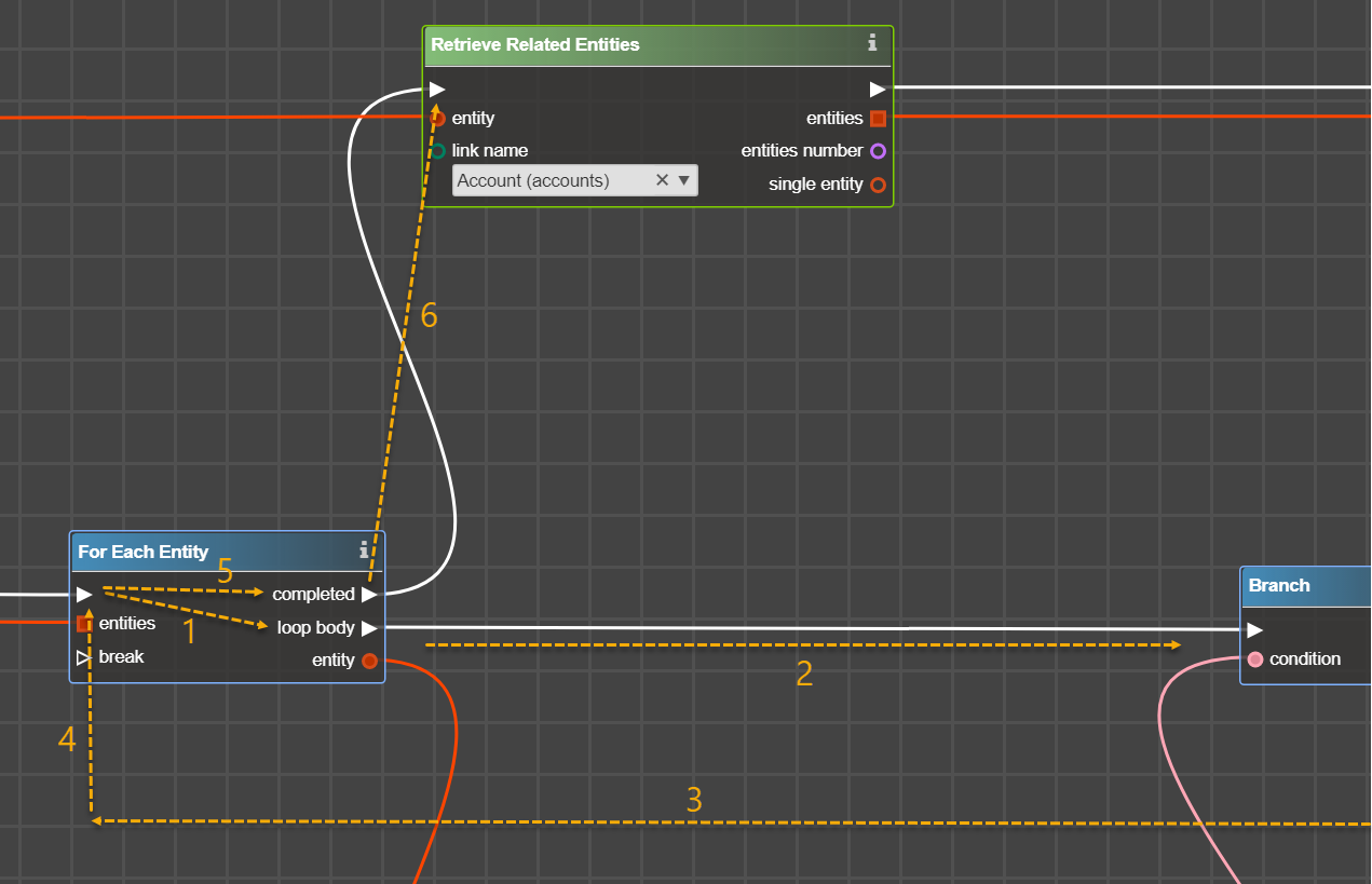
Assume that you have 2 entities in the input port Entities in For Each Entity Operator. Control Flow will go through links 1->2->3->4->1->2->3->4->5->6
Also For Each Entity and For Each element have one more control input port – break. In case of control flow comes from break – it will go directly on the completed port even if there are items in the input port.
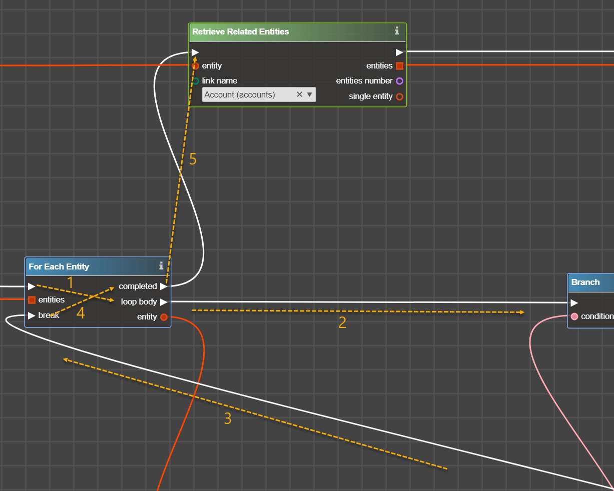
In this example control flow will go through 1->2->3->4->5. After 3 we have ‘break’ which means exit the loop.
Data Ports and Data Flow Links
Colored (not white) ports are called Data Ports and a link between them is called Data Flow Link.
The operator may have only data ports, without control ports. However, those operators are only executed when their outputs are eventually connected to an operator that does have control ports.
Link data ports with data flow link. Keep in mind several rules for data flow links and ports:
1. You can link as many as you need data flow links from data port
2. You cannot submit contradictory inputs to the input data port. This means that you can link several data flow links in one data port. But you must be sure that there is the same input in any case.
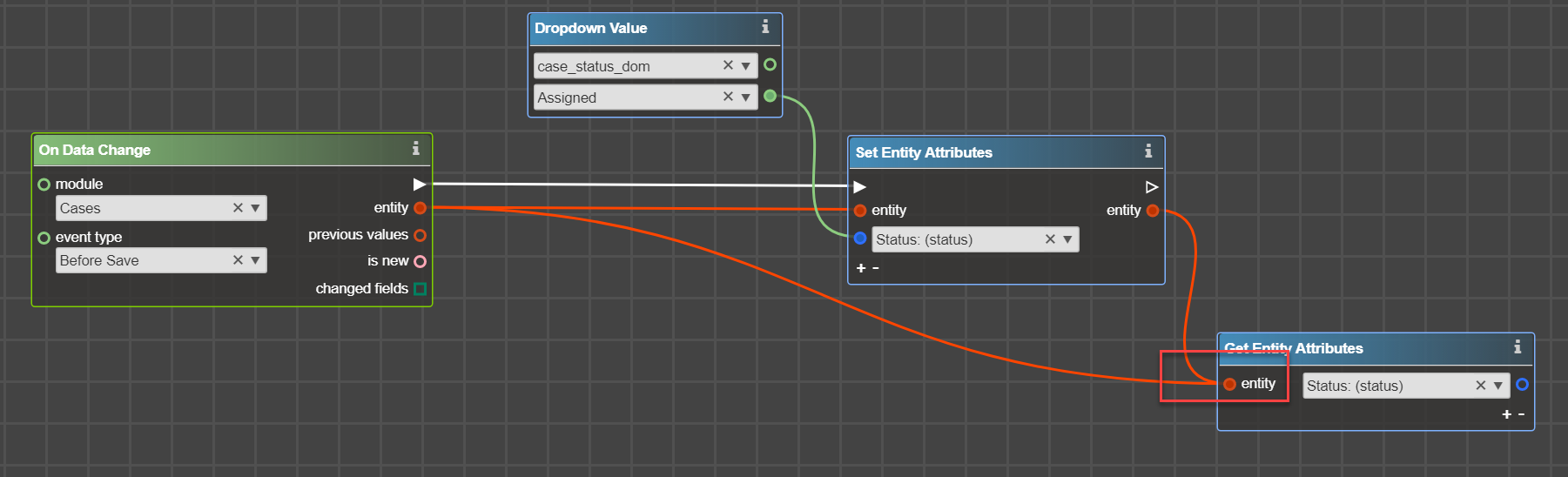
You cannot do something like on example above. In Get entity attributes you will have two different entities, which will cause the flowchart work unexpectedly.
Data Port Shapes
There are two data port shapes:

Circle – means that you have only one item in this port – field, value, entity, constant, element, etc.

Square – means that you have one or more items here – several entities, several elements. Usually, you do not want to connect square ports to round ports, but this is not prohibited. E.g. when you are sure that there is only one entity in square entity port, you can connect with the circle port. Another example is if you would like to output collection or array elements into LOG.
Data Port Colors
The color of each port is a reminder to you what you can expect in output or what you should submit in the input. It is more like guidance, rather than a rule – you can connect ports of different colors. Please follow the guidelines for each operator to find out more about what you can input and what can be output.
| Port | Data | Comments |
| entity | You have one (if round) or several (if square) entity(-ies) in output port or you need to input entity. | |
| boolean | You have true or false in output or operator expects true or false as input. | |
| dropdown | ||
| any data | ||
| string | ||
| number | ||
| structure or special type (like service) | ||
| date |
Filled data in Data Ports
Some operators may require inputting data directly in the operator. There are some types of possible input data.
Dropdown

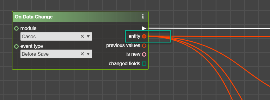
This means that you should select something from the list. Example – Get Entity Attributes, On Data Change, Dropdown Value.
After placing operator with a dropdown in Workplace – some lists are filled with values, but sometimes – not. If your dropdown list is empty – make sure:
- That you submit input port.
Example: Set Entity Attributes. The dropdown list is empty until you specify entity in the input port.
- That you specify another dropdown.
Example: Dropdown constant. Until you choose the dropdown name in the first line – the second one will be empty.
Input Value

This means that you should type something. It may be a symbol (separator for custom collection), string (a subject for email), number – actually, any value that you want.
It is not required to input data directly in a operator , you can also link input data:
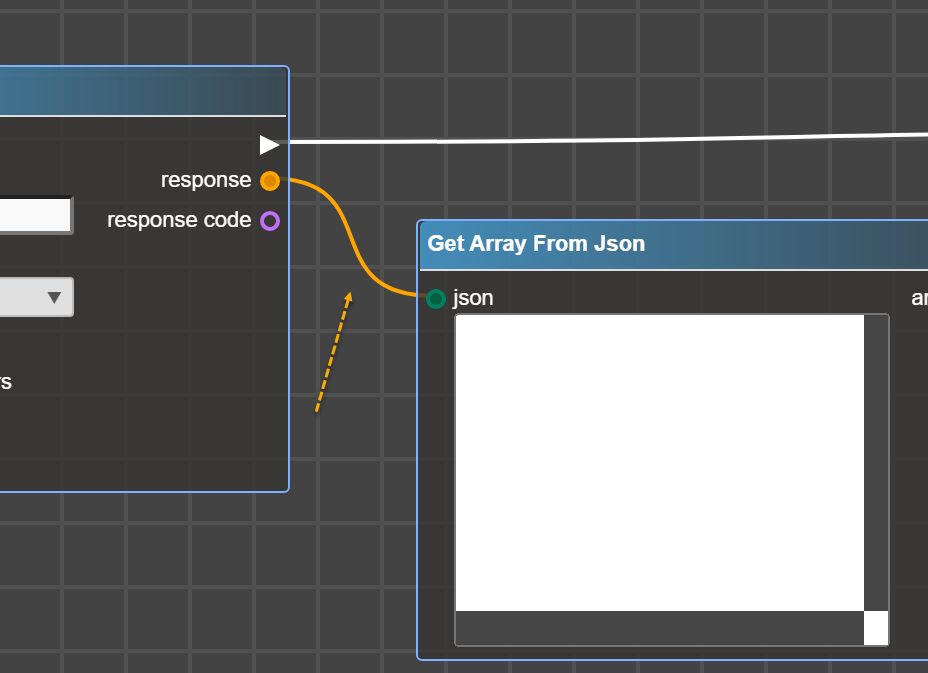
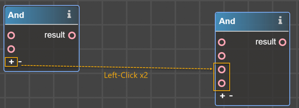
Extend Operators’ Input Ports
Some operators allow you to submit several inputs value.
For this purpose, you will see symbols ‘+’ – to add input, ‘-‘ – to remove inputs: